

Many buildings in the region that are now treated as heritage were built in the second half of the twentieth century with hollow concrete block masonry, plastered and finished to look like traditional construction. A number of them are being restored and given new uses. Internal arcades are a common feature: rows of pointed arches carried on slender, often tapered, piers. When these buildings are surveyed, cracking at the base of the piers is a frequent finding, and the question for the engineer is whether the cracks point to a structural problem, a material problem, or both.
We recently modelled a representative arcade of this type to study the problem. This note summarises the approach, what the stress results show, and how they inform retrofit decisions. The geometry and material values are representative and do not describe a particular building.
The model
The arcade was modelled in SAP2000 as a plane wall of shell elements: pointed arches spanning between tapered piers, with the wall above included and each pier restrained along its full base. The material was defined as filled hollow concrete block masonry, with a unit weight of about 19 kN/m³ and an elastic modulus taken from Eurocode 6 (E = 1000 fk), which for low-strength block masonry gives roughly 2,000 to 3,000 N/mm². The analysis is linear elastic under self-weight, which governs for a heavy masonry wall of this kind.
Two modelling choices matter more than they appear to. The first is the material. A model left with a default concrete material still gives the right stress pattern under gravity, because the stresses in a uniform linear model do not depend on the elastic modulus. Its strains, deflections and natural periods, however, will be wrong for masonry, and its self-weight will be overstated by 20 to 25 percent. The second is the supports. Restraining each pier at a single node produces a local stress peak that keeps growing as the mesh is refined. That peak is a numerical artifact, not a property of the structure, and in an early run it dominated the results. Supports should be spread over the full base of the pier, and values right at a support or at the cut ends of the model should not be quoted.
What the stresses show
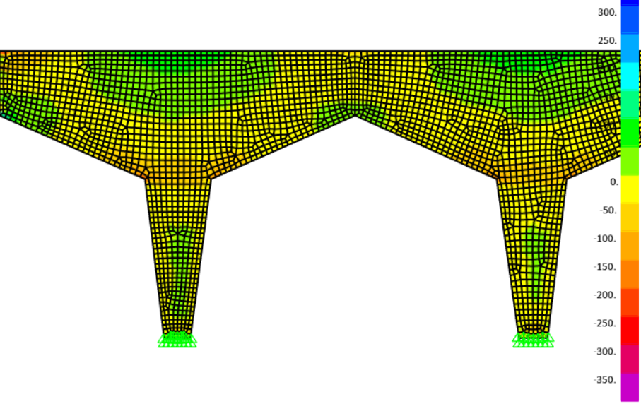
Figure 1. Horizontal stress (S11) under self-weight, kN/m². Compression along the arch and at the pier heads, mild tension in the pier cores, and the highest tension at the top of the wall over the piers.
Horizontal stress. The masonry following the arch is in horizontal compression, of the order of 50 to 150 kN/m², strongest where the arch meets the pier. This is the arch working as intended: the thrust stays within the section and is carried down into the piers. The faces of the piers are in compression and their cores in mild tension, about 17 kN/m² (0.02 N/mm²). Right at the base, the restraint of the footing puts the masonry into horizontal compression. The highest horizontal tension in the model, about 50 to 100 kN/m², is at the top of the wall over each pier, where the wall hogs over its supports like a continuous deep beam.
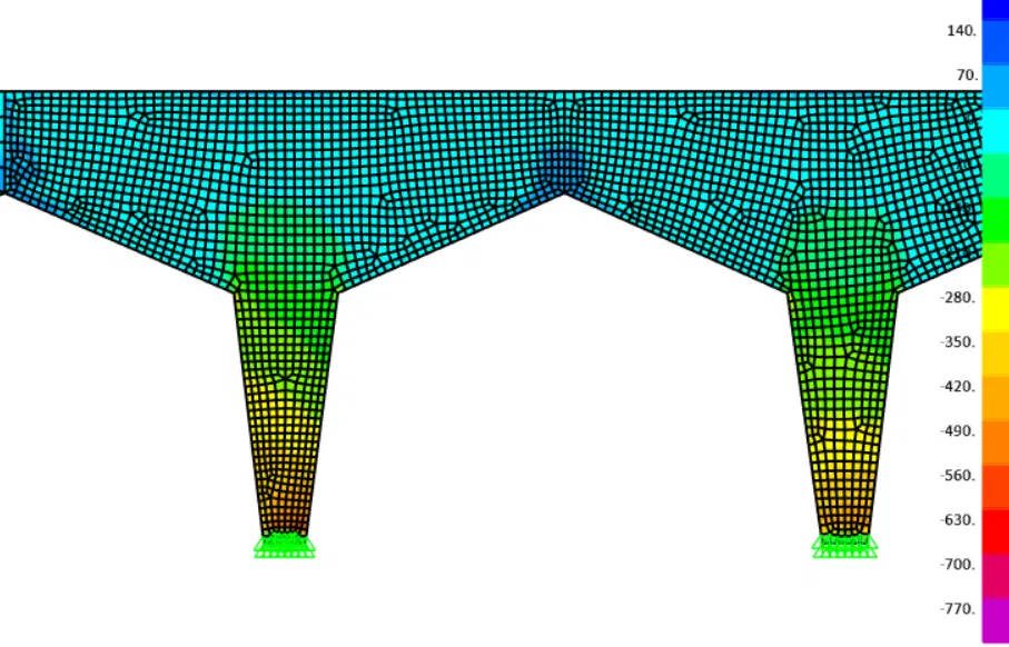
Figure 2. Vertical stress (S22) under self-weight, kN/m². Compression builds down each pier to about 500 to 600 kN/m² at the base.
Vertical stress. Vertical compression is low across most of the wall, below about 70 kN/m². Above the crown of the arch it falls to zero or slight tension, because the load flows around the opening rather than through it. In the piers, compression builds up towards the base, where the section is smallest, and reaches about 500 to 600 kN/m² (0.5 to 0.6 N/mm²).
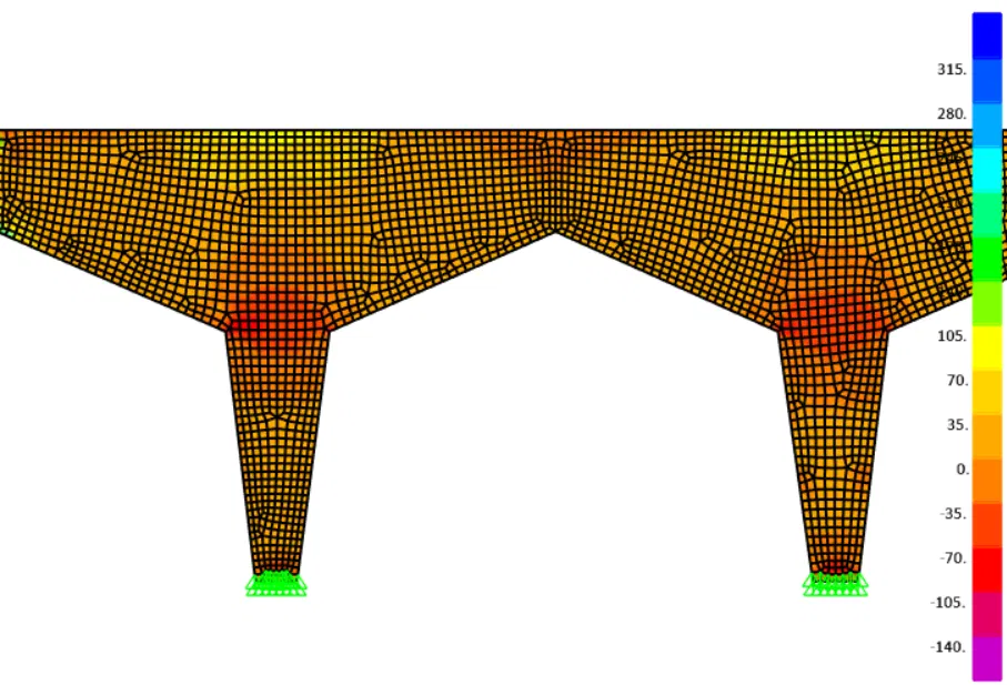
Figure 3. Maximum principal stress (Smax) under self-weight, kN/m². Biaxial compression at the pier heads, low principal tension elsewhere.
Principal stress. The pier heads, where load is collected from the wall into the piers, are in biaxial compression. Principal tension is low throughout, mild in the pier cores and highest at the top of the wall over the piers, consistent with the horizontal stress plot.
What the model says, and what the building says
Compared with the capacity of filled hollow block masonry, these stresses are low. Vertical compression of about 0.5 N/mm² at the pier base is a modest fraction of a compressive strength that is typically a few N/mm². Tension of about 0.02 N/mm² in the pier core is well below the tensile strength of block masonry, which is of the order of 0.05 to 0.1 N/mm². On the model’s evidence, a sound pier carries its own weight without cracking.
Yet in buildings of this type the cracking starts right at the base of the piers, where the model shows horizontal compression rather than tension. That mismatch is the most useful result of the analysis. When a model says a structure should be sound and the building says otherwise, the cause lies in something the model does not contain. At the base of a pier, the usual candidates are:
- Decay of the lowest courses. Rising damp and salt crystallisation attack the bottom of a wall first, particularly in coastal climates, and can reduce the strength of block and mortar to a fraction of its original value.
- The base bed joint. The first mortar course, or a damp-proof layer, is a natural plane of weakness.
- Foundation movement. Settlement or rotation of a pier footing, whose size is usually unknown.
- Corrosion of embedded steel. Reinforcement or dowels in the filled cores expand as they corrode and split the block around them.
- Unfilled cores. Hollow blocks were sometimes left unfilled, which reduces both capacity and stiffness locally.
The orientation of the cracks narrows the list. Horizontal cracks along the base joint point to the joint itself, to rotation or to settlement. Vertical splitting through the lowest blocks points to material decay, salts or corrosion. Diagonal cracks point to settlement. The model can then be used to test each hypothesis, for example by imposing a small settlement under one pier, or by reducing the stiffness and strength of the bottom courses, and checking which case reproduces the observed pattern.
The model also points to where else to look. The highest tension it predicts is at the top of the wall over the piers. Where no slab or ring beam ties the wall at that level, vertical cracks there would be expected, and they should be checked during the survey.
Retrofit options
Retrofit of a heritage building follows three principles: minimum intervention, compatibility with the existing materials and, where possible, reversibility. Because the analysis shows that the piers are not overstressed by gravity, the emphasis is on the cause of the damage rather than on adding strength. The options we consider are:
- Removing the cause first. Where moisture and salts are involved, drainage, damp-proofing and salt reduction come before any repair. Otherwise repairs tend to fail within a few years.
- Repairing the base. Decayed blocks in the lowest courses are cut out and replaced, the base joint is repointed with a compatible mortar, cracks are injected with a compatible, low-strength grout, and empty cores are filled where they are accessible.
- Confinement of the pier base, where splitting or loss of section has occurred, with steel bands or textile-reinforced mortar (TRM). On masonry, TRM is generally preferred over epoxy-bonded FRP because it is more compatible with the substrate and allows the wall to breathe.
- Foundation stabilisation, where the survey confirms settlement or rotation of a footing.
- Restraint at the top of the wall, with a discreet tie or ring beam, where tension cracking is found over the piers.
- Monitoring. Crack gauges installed before and after the intervention show whether the cracks are active and whether the repair is working.
The analysis is then repeated with the retrofit in place. A linear model only shows where cracking will start. For capacity checks beyond that point, a nonlinear masonry model or a thrust line (limit) analysis gives a more realistic picture.
How we approach these assessments
At MAA, assessment of existing and heritage buildings combines geometry capture, testing and analysis. Geometry comes from our own drone LiDAR and photogrammetry survey (see drone-based mapping), processed into a point cloud and a BIM model that also records the crack pattern. Material properties are taken from testing where possible and from code values otherwise. The structural model is built from both, and its results are read against what is observed on site. More on our structural and architectural services.
If you are dealing with cracking in an existing masonry building, send us photographs and any drawings you have and we will advise on the scope of assessment needed. Contact us.